DC Brushless Cooling Fan Behavior
![]()
What Your Fan Data Sheet Isn’t Telling You
DC Brushless cooling fans have a long history of being an effective method of cooling electronic circuits. Today, DC brushless cooling fans are found in new applications and are being evaluated by engineers that may not have previously used fans in their products. These engineers may not be familiar with all of the “undocumented features” that are inherent to these types of fans. If the engineer is not familiar with all the characteristics of air moving devices, they could be in for a nasty surprise.
Let’s look at some examples.
Speed Changes with Input Voltage
Fan manufacturers typically specify the nominal speed of the fan, as well as an operating voltage range. In Figure 1, the datasheet shows the rated voltage as 12 Vdc and the operating voltage range as 6 -18 Vdc. What may not be clear is that all the performance characteristics of the fan, especially speed and airflow, correspond to the rated voltage of 12 Vdc. If the voltage to the fan is decreased from this value, the speed and airflow will also decrease.
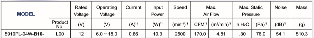
Figure 1: data sheet information
DC Brushless Cooling Fan Behavior
As an example, if the fan in Figure 1 was operated at 9 Vdc instead of 12 Vdc, the speed would not be 2500 RPM, but closer to 1300 RPM. Also, the airflow would not be 170 CFM, but closer to 88 CFM. In order to minimize the effects of this, engineers should be sure to minimize voltage drops across power leads and verify the power supply voltage is well matched to the fan application.
Speed Tolerances
In the above example (Figure 1) the speed is given as 2500 RPM. This value is the nominal speed at the rated voltage (12 Vdc). The datasheets from fan manufacturers may not clearly state this value has a tolerance associated with it. Tolerances vary from manufacturer to manufacturer, but tolerance of + 10% is typical. For example, if the fan was to fall on the lower end of the tolerance (so at 12 Vdc the fan was rotating at 2250 RPM) the airflow at free air is the only 153CFM. This potential decrease in airflow must be considered in the system cooling design.
Current draw by a DC fan motor
When examining the label on a DC brushless fan or examining a datasheet, the value for the current draw will be given as an average current. What may not be understood is the current draw from this fan is not a DC current. A typical current waveform is shown in Figure 2 below.
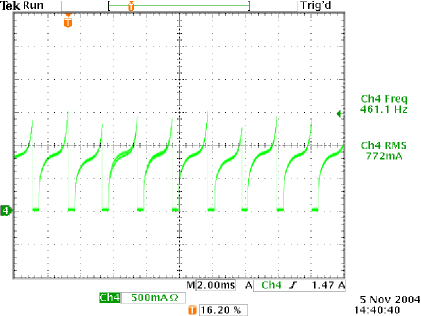
When designing the electronics that interface to a DC brushless cooling fan, it is critically important to be aware of this behavior. Fan peak current draw can be very significant, especially if the ground circuitry is shared with low-level digital logic circuitry. Large switching power currents sharing grounds with low-level digital logic create problems for the digital logic. Also, these large switching currents can create ripple voltage on a DC line if not properly filtered.
Changes in fan characteristics as system pressure changes
The current and speed of a fan as presented in a datasheet are measured in a free air condition. This is the easiest way to measure these fan parameters, but it is an unfortunate choice, as no fan application will actually be operating in a free-air environment. Once a fan is installed into a system, it will be subject to the pressure of that system.
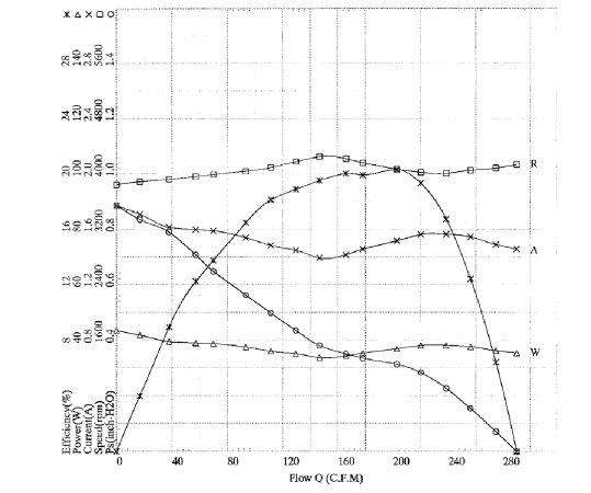
Figure 3: Typical fan PQ curve
A typical PQ curve (flow vs. pressure) of an axial fan is shown above. As this graph shows, the current draw and speed of the fan is not constant with increasing pressure. Looking at the current draw, we can see the current actually increases with increasing pressure before decreasing again. Engineers using fans must be aware of this phenomenon and size of the power supply accordingly.
Also of note is that the speed is not constant with increasing pressure. This can be important if monitoring the tachometer signal of the fan and set alarms based on measured speed.
In a typical fan datasheet, only the airflow and pressure curve is shown. It is best to ask the manufacturer for the complete PQ curve to design the system cooling accordingly. Keep in mind that the PQ curve characteristics will vary among different air moving devices (axial, blowers, etc).
Vibration in fans
In an ideal world, we could perfectly balance all rotating devices so there was no vibration. Unfortunately, this is not yet possible and fans are similar to all rotating devices in this aspect. Depending on the level of balance and the speed of the fan, there will be some level of vibration generated by the fan product.
Isolation between the fan and the structure it is mounted to should be considered in every system design to reduce the effects of the fan vibration. Also, be aware of any possible resonances between the frequency of rotation of the fan and the mounting structure. We have seen situations were these resonances have created up to 5 dBA of additional acoustic noise at the system level.
Fans in stall
There is region in the PQ curve of axial fans that is commonly referred to as the “stall” region. This is a complex phenomenon and will not be covered in detail in this article, but the effects of this region should be understood by the system engineer.
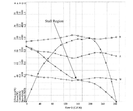
Figure 4: PQ curve with Stall Region marked
One result of the stall of the blade is that if the fan is operating in a high-pressure region, the exit direction of the air moves away from the axial direction and approaches a diagonal direction (Figure 5). This creates problems if the items to be cooled are placed on the same axis as the fan. Keep this in mind when designing the cooling solution to ensure the proper areas receive the maximum airflow.

Summary
Electronic products are widely understood to have important characteristics that may not appear on a data sheet. DC brushless cooling fans are no exception to this rule. The only way to prevent unforeseen problems in a cooling design is to ask questions about the above fan behaviors to your chosen fan vendors.
NMB Technologies Corporation is a MinebeaMitsumi Group company; the world’s largest manufacturer of NMB miniature ball bearings and a volume leader in the design and manufacturing of precision electro-mechanical components, backlight and LED lighting products and advanced technology solutions for smart cities, medical automotive and industrial markets.
![]()
NMB Technologies Corporation
A MinebeaMitsumi Group Company
39830 Grand River Avenue
Novi, MI 48375
USA
Tel: 248-919-2250
Email: info@nmbtc.com
Web: nmbtc.com