Ball Bearing Engineering
Ball Bearing Introduction – Names & Symbols
A ball bearing is composed of an outer and inner ring, balls and a retainer. It is also available with shields, seals, flanges, and snap rings.
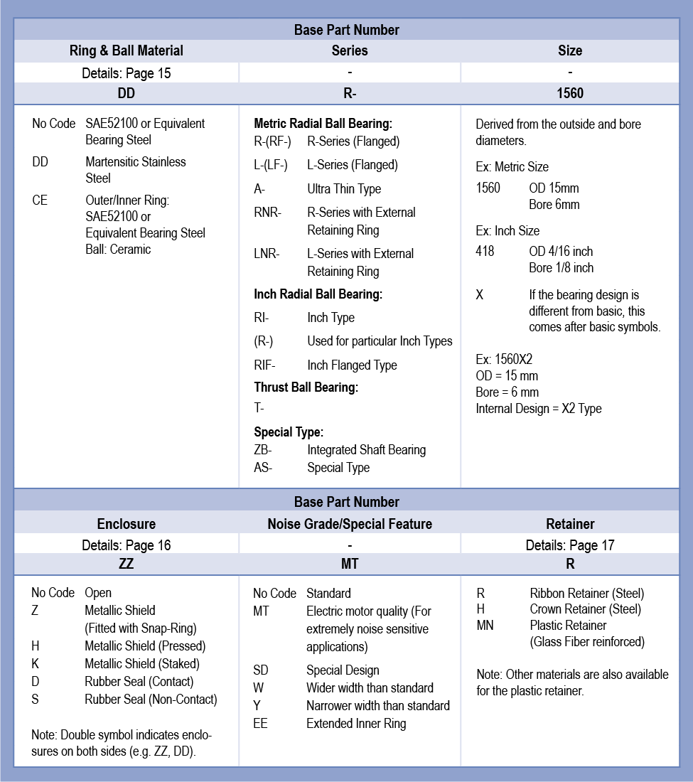
Ball Bearing Part Numbering System
The NMB Part Numbering System is comprised of the base part number and specification. The NMB Part Numbering system is unique to Minebea. JIS Part Numbering is based on a system that is defined in the JIS 1513 standard.
Application Conditions, Environment, Required Performance
The structure of the application, dimensions of the equipment or component which the bearing will be assembled to, and the application environment and conditions need to be confirmed. It is necessary to take several factors into account in order to decide the bearing part number and specification. It is also important to take market factors into account for selecting the bearing part number and specification.
Structure & Function of the Equipment
The required dimensions and performance need to be based on an understanding of the structure and function of the equipment. Structure limitations are becoming more severe due to downsizing of applications. We recommend taking into account the items listed below and selecting properly to achieve the required bearing performance.
Application Environment
The bearing material, retainer and lubricants are selected based on the ranges of predicted temperature and humidity. The proper preload and lubricant are selected based on the vibration conditions. The presence of dust influences the selection of the shield or seal type. Depending on the operation conditions, bearing temperature is occasionally higher than environmental temperature.
Loads
The bearing dimension (Part Number) is selected based on the magnitude, position, and direction of loads applied to the bearing. It is necessary to review the structure of the equipment to determine if excessive loads would be applied to the bearing. If so, select a larger size bearing or decrease the loads.
Material and Dimensions of the Shaft and Housing
The dimensions and tolerances of the bore diameter, outer diameter, and width are selected based on the dimensions and material of the shaft and housing. Temperature changes can affect the bearing internal clearance if there are differences in linear expansion coefficients of the shaft, housing, and bearing materials.
Speed, Rotation Precision, Rotation Ring
Dimensional tolerance, retainer, clearance, preload, and lubricant are selected based on speed, rotation precision, and rotation conditions (continuous/intermittent/ back and forth/outer or inner ring rotation).
Torque
Torque can be classified into either starting torque or running torque. When an application is torque-sensitive, enclosure types, lubricant types, fill amount, and retainer types need to be considered carefully.
Noise
When an application is a noise sensitive, it is necessary to take bearing noise characteristics, lubricants and preloads into account. Care must be taken during installation and handling. Improper installation, handling damage, or contamination could worsen the noise level.
Life
Although rating life is defined in JIS B 1518, life can be defined in various ways because it is affected by the application and the progress of degradation for the required performance level (noise, torque, runout, etc.) for each customer. The various types of life include rating life, noise life, performance life, and lubricant life.
Regulated Substances
In recent years, various regulations have been established for environment, health and safety. It is necessary to confirm if regulated substances listed in the laws are present or not. Substances harmful to the environment and humans are restricted.
Material
Ball bearing performance is significantly influenced by the selection of the proper material for components such as balls, inner and outer rings.
Bearings are exposed to severe stress. The contact area of the outer and inner rings, as well as the balls, are repeatedly exposed to stress exceeding 1,000 MPa. Material type, purity, and hardness are very important factors for long bearing life under repeated high stresses.
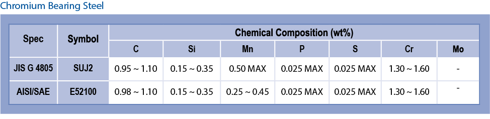
High carbon chromium bearing steel and high corrosion-resistant martensitic stainless steels are used for raceway rings and balls in our products.
High carbon chromium bearing steel rings and balls are made from high-quality vacuum outgassed steel (JIS G 4805, SUJ2, AISI/SAE52100 or equivalent material). With proper heat treatment, they have high load capacity, longer life and low noise levels.
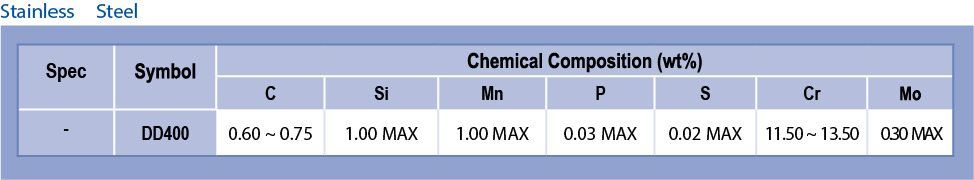
Minebea developed stainless steel “DD400.” The hardness of DD400 after heat treatment is higher than that of SUS440C. The DD400 material also shows longer life, and high load capacity.
The noise level of DD400 material is close to that of chromium steel because the carbon is dispersed spherically. From the results of tests based on ASTM-A380, the corrosion resistance of DD400 material is equal to SUS440C.
To meet longer life and low noise level requirements, ball bearings with ceramic balls are also available. When compared to the conventional chromium bearing steel balls, improved noise level and life can be achieved by using ceramic balls (Silicon Nitride) with the use of conventional chromium rings. The extremely low conductive characteristics (insulation properties) of silicon nitride protect bearings from electric corrosion, which is generated under a conductive environment. In addition, torque reduction can be expected because the ceramic has less mass than bearing steel.
Chemical Composition of Materials
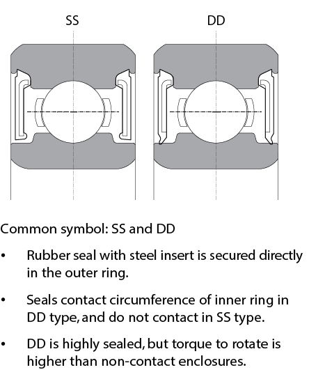
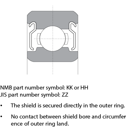
Shields and Seals
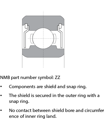
Shield
Retainer
Ribbon Retainer
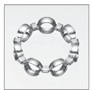
Composed of two stamped steel parts. The balls
are held between the two steel parts and the tabs
of one of the steel parts are bent over the second
steel part to fasten them together. This is the most
common type.
Plastic Retainer
Composed of molded or machined plastic, including
Polyamide, Polyacetal and others. It is used for high
speed rotation and low noise level.
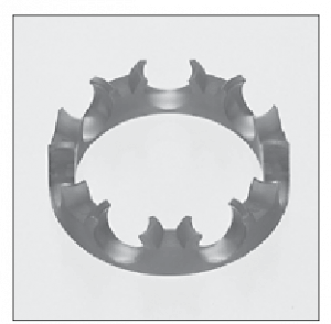
Crown Retainer
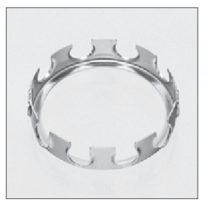
Composed of a stamped steel part. The small
difference in inner and outer diameters of the
retainer allows them to be used for thin type
and very small ball bearings.
Load Rating and Life
In general, if bearings are made of high quality steel with high level production skills, the load rating and rating life can be calculated based on the specification defined in JIS and ISO.
Life of a Ball Bearing
The required life of a ball bearing depends on the application and requirements of the equipment. Because there are many different applications for the equipment, definitions of life also vary. Therefore, life needs to be defined based on the application and requirements.
There are different types of life definitions: rating life, noise life, lubricant life, and performance life. The noise life is considered when bearings become noisier than the originally set level. The lubricant life is considered as when lubricants lose their function due to degradation. The performance life is considered when speed and runout go beyond the acceptable limits and no longer meets the application requirements.
In this section, the rating life of single row deep groove ball bearings, which is specified in JIS B 1518, is explained. Rating life is a predicted life calculated based on the basic dynamic radial load rating.
Basic Rating Life (L10)
Defined as the life associated with 90 percent reliability.
According to ABMA Std. 9, for an individual bearing, or a group of apparently identical bearings operating under the same conditions, the life associated with 90% reliability, with contemporary, commonly used material and manufacturing quality, and under conventional operating conditions.
The calculation is based on JIS B 1518

If the speed is constant, the life is usually expressed in hours. The relationship between basic rating life and life hours is as follows:

Basic Dynamic Radial Load Rating (Cr)
Defined as the calculated, constant radial load that a group of apparently identical bearings will theoretically endure for a rating life of one million revolutions. The calculation is explained in JIS B 1518. The Basic Dynamic Radial Load Ratings are for reference only.
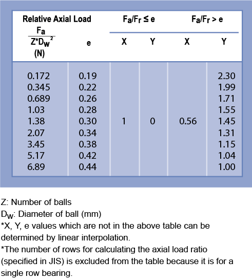
Dynamic Equivalent Radial Load (Pr)
Bearings subjected to primarily dynamic radial loads are often also subject to some axial force. To interpret this combined radial and axial load it is convenient to consider a hypothetical load with a constant magnitude passing through the center of the bearing. This hypothetical load is referred to as the Dynamic Equivalent Radial Load and is calculated with the following equation.

Calculation Example
Under the conditions below, the L10 life of an R-830ZZ bearing is calculated.


Basic Static Radial Load Rating (Cor)
The static radial load rating (Cor) given on the product listing pages is the radial load which a nonrotating ball bearing will support without damage, and will continue to provide satisfactory performance and life.
The static radial load rating is dependent on the maximum contact stress between the balls and either of the two raceways. The load ratings shown were calculated in accordance with the ABMA standard. The ABMA has established the maximum acceptable stress level resulting from a pure radial load, in a static condition, to be 4.2 GPa (609,000 psi).
Static Equivalent Radial Load (Por)
For a stationary or slowly rotating bearing, the theoretical static radial load that produces the same contact stress at the area of contact between the most heavily stressed ball and raceway, as the contact that occurs under the actual load conditions.
Using the calculations below, the larger of the two values should be used as the Static Equivalent Radial Load

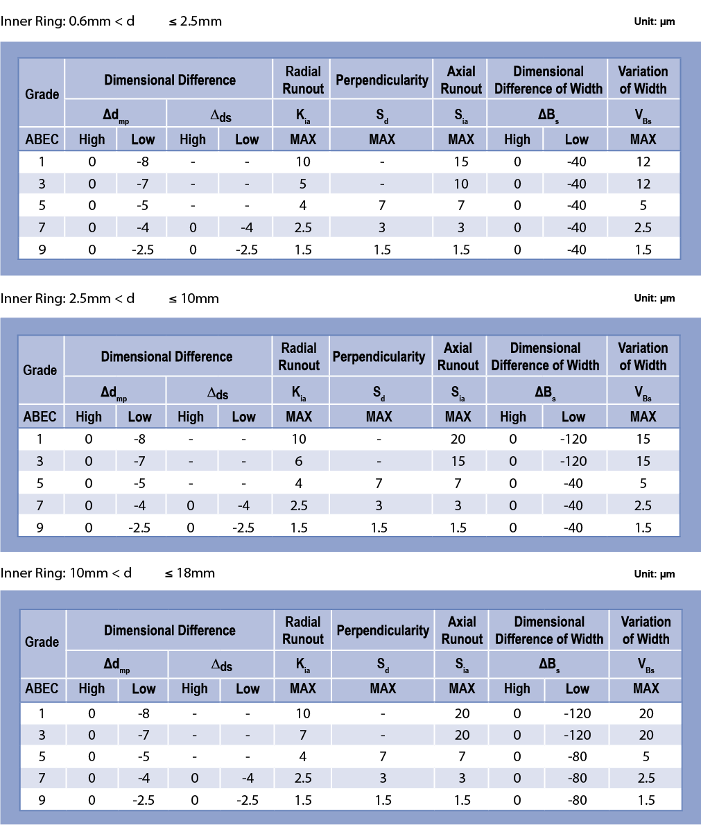
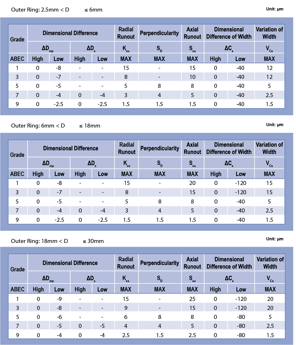
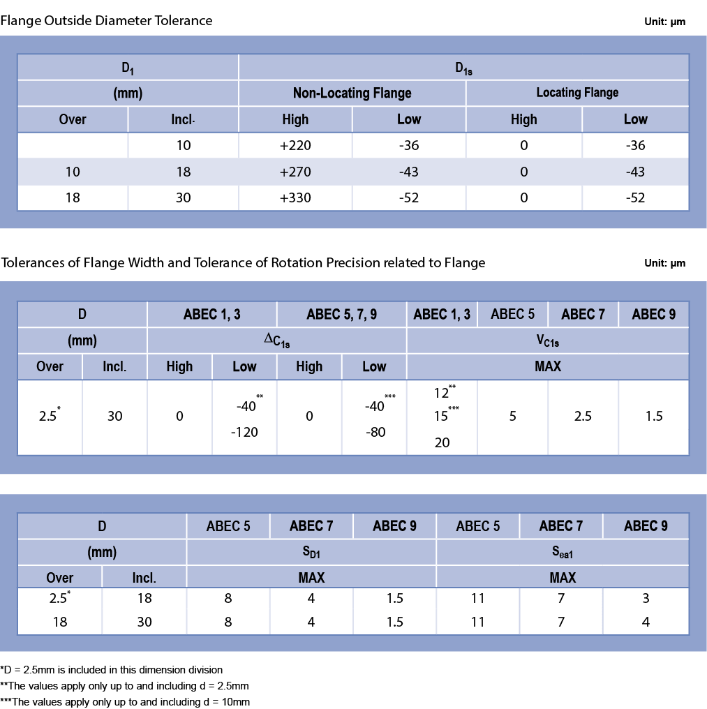
Tolerance and Precision Grade
Bearings are classified into certain precision grades. The tolerances for each grade are found in JIS and ANSI/ABMA standards. Minebea’s products are based on JIS B 1514-1,-3, ANSI/ABMA Std. 12.2 and ANSI/ABMA Std. 20.
The symbols used in the specification are as follows:
Symbol
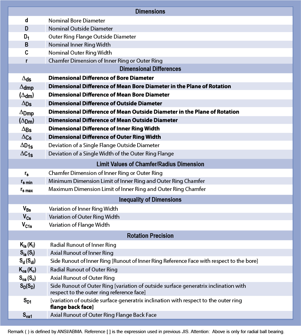
Referenced from ANSI/ABMA Std. 20
Referenced from ANSI/ABMA Std. 20.0
Referenced from JIS B 1514-1
Referenced from JIS B 1514-3

Measurement Methods
General rules regarding verifying ball bearing dimensions and runout are specified in JIS B 1515-2. Please refer to the following for the dimensions and measurement methods of runout.
Bore (ds) ………………………………………………………………………………….. Figure 2-1
Outer Diameter (Ds) ……………………………………………………………….. Figure 2-2
Inner Ring Width (Bs) …………………………………………………………….. Figure 2-3
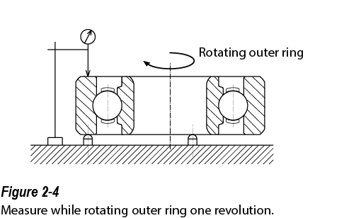
Outer Ring Width (Cs) ……………………………………………………………. Figure 2-4
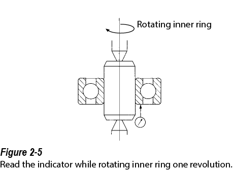
Side Runout of Outer Ring (Sd) …………………………………………….. Figure 2-5
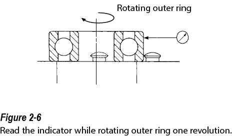
Outside Cyl. Surface Runout w/ Side (SD) …………………………… Figure 2-6
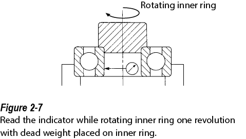
Radial Runout of Inner Ring (Kia) …………………………………………. Figure 2-7
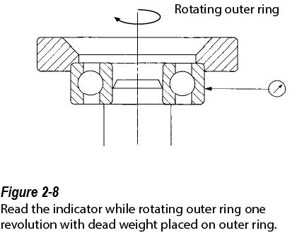
Radial Runout of Outer Ring (Kea) ……………………………………….. Figure 2-8
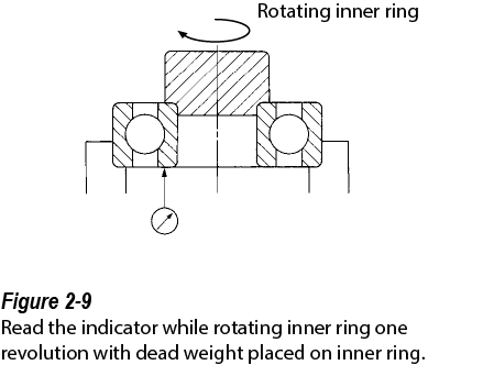
Axial Runout of Inner Ring (Sia) ……………………………………………. Figure 2-9
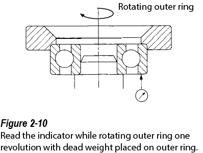
Axial Runout of Outer Ring (Sea) ………………………………………….. Figure 2-10
Dimensions


Radial Internal Clearance
The radial internal clearance of a ball bearing affects life, noise, vibration, and heat generation. It is important to select the appropriate internal clearance for each application.
The three types of internal clearance of a ball bearing are radial clearance, axial clearance, and moment clearance.
Radial internal clearance decreases when a ball bearing is fitted to either a shaft or housing with interference. Radial internal clearance is a specified value in the NMB or JIS part number, as shown in the following tables.
The fits and temperature affect the radial internal clearance. Therefore, actual application conditions need to be reviewed when radial internal clearance is selected.
Radial Clearance
![]()
Axial Clearance
![]()
Moment Clearance
![]()
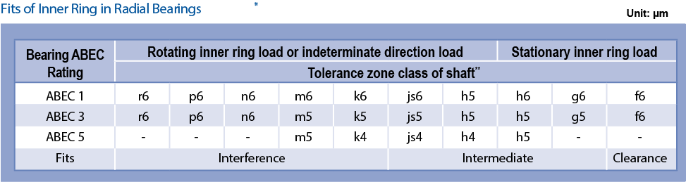
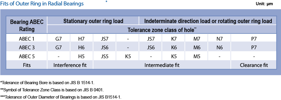
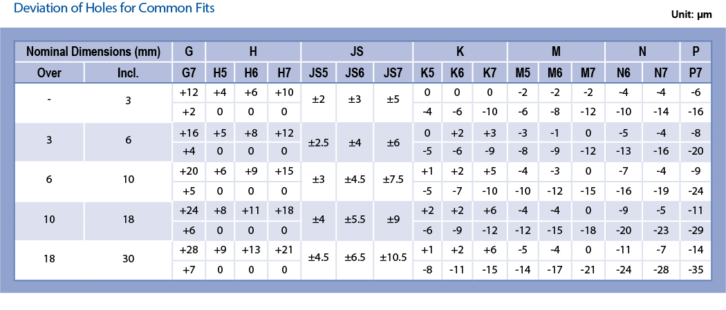
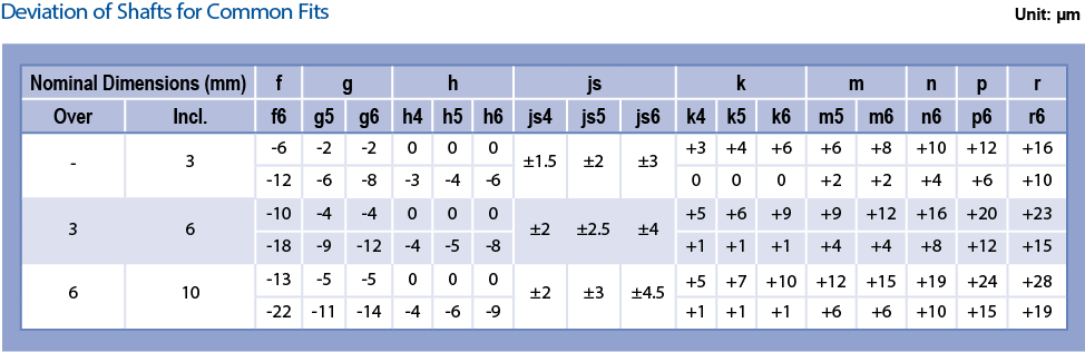
Fits
When a ball bearing is used, it is not used only by itself. It is always fitted to either a shaft or a housing bore. Fit is the value of tightness between the shaft and bearing bore when the bearing is installed. Fit can also be the tightness between the housing bore and the bearing outside diameter. Fits are classified into clearance fit, intermediate fit, and transition fit. Fits
Fits prevent bearings from having unfavorable slip called “Creep” by firmly securing the inner ring and outer ring on the shaft and in the housing, respectively. Fits also minimize vibration during rotation. When creep happens, abnormal heat and wear particles can be generated. Abnormal heat hastens the degradation of grease and retainers. Wear particles could migrate inside the bearing, and cause vibration and surface degradation. It is necessary to choose a proper fit for each application because improper fits can not only degrade the bearing performance, but also they could cause seizure due to heat generation and premature failure. In the case of interference fits, the interference causes a change in radial internal clearance. The change in radial clearance generated by interference can be calculated as shown below. Decrease in Internal Clearance Due to Fits
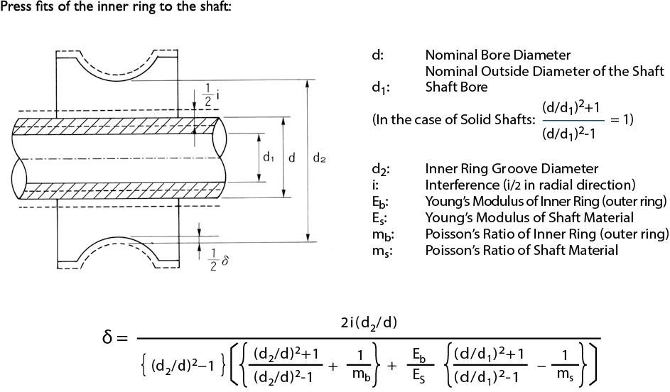
Interference Fit of the Inner Ring to the Shaft
The sketches drawn in solid lines and dotted lines are the bearing prior to fit, and the bearing after fit, respectively. When press fit with an interference (i) the inner ring groove diameter (d2) increases by an amount (δ). This value (δ) is also equal to the decrease in radial internal clearance.
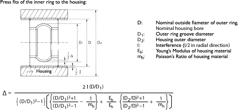
Interference Fit of the Outer Ring to the Housing
The sketches drawn in solid lines and dotted lines are the bearing prior to fit, and the bearing after fit, respectively. When it is press fit with an interference (I) the outer ring groove diameter D1 decreases by an amount (∆). This amount (∆) is also equal to the decrease in radial clearance.
Securing with Adhesive
When the bearing is fit to the shaft and housing with adhesive without interference, it is necessary to select the proper clearance to enhance the effectiveness of the adhesive. It is recommended to consult with the adhesive manufacturer because the proper clearance depends on the type of adhesive. Please be aware that the roundness of the ring raceways could deteriorate due to the curing stress of the adhesive.
Referenced from JIS B 1566
Referenced from JIS B 0401-1
Definitions
Rotating Inner Ring Load: The line of action of the load is rotating in relation to the inner ring of the bearing
Stationary Inner Ring Load: The line of action of the load does not rotate in relation to the inner ring of the bearing
Stationary Outer Ring Load: The line of action of the load does not rotate in relation to the outer ring of the bearing
Rotating Outer Ring Load: The line of action of the load is rotating in relation to the outer ring of the bearing
Indeterminate Direction Load: The direction of the load cannot be determined
Designs of Shaft and Housing
Finish Precision of Shaft & Housing
When the bearings are installed, roundness of the bearings is degraded if the precision and surface roughness of the shaft and housing are not at satisfactory levels.
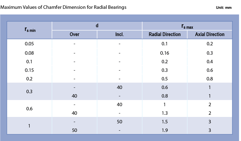
Fillet Radii of Corners of Shaft & Housing
The side faces of the shafts and housing (areas contacting the bearing’s side face) should be at right angles to the shaft center line and fit surfaces. The maximum permissible radius (ras max) of the fillet radii of the shaft and housing corners is smaller than or equal to the minimum permissible chamfer dimensions of the bearings.
Height of Shoulder
The height of the shaft and housing shoulders must be taller than the minimum permissible chamfer dimensions. They also need to contact the side faces of the bearing inner and outer rings. The minimum height of the housing shoulder (h), must be four times the chamfer dimension (ras). Please refer to the table below and Figure 2-14 for dimensions.
Referenced from JIS B 1566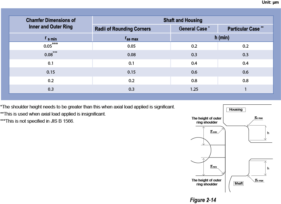
Shaft and Housing IT Grades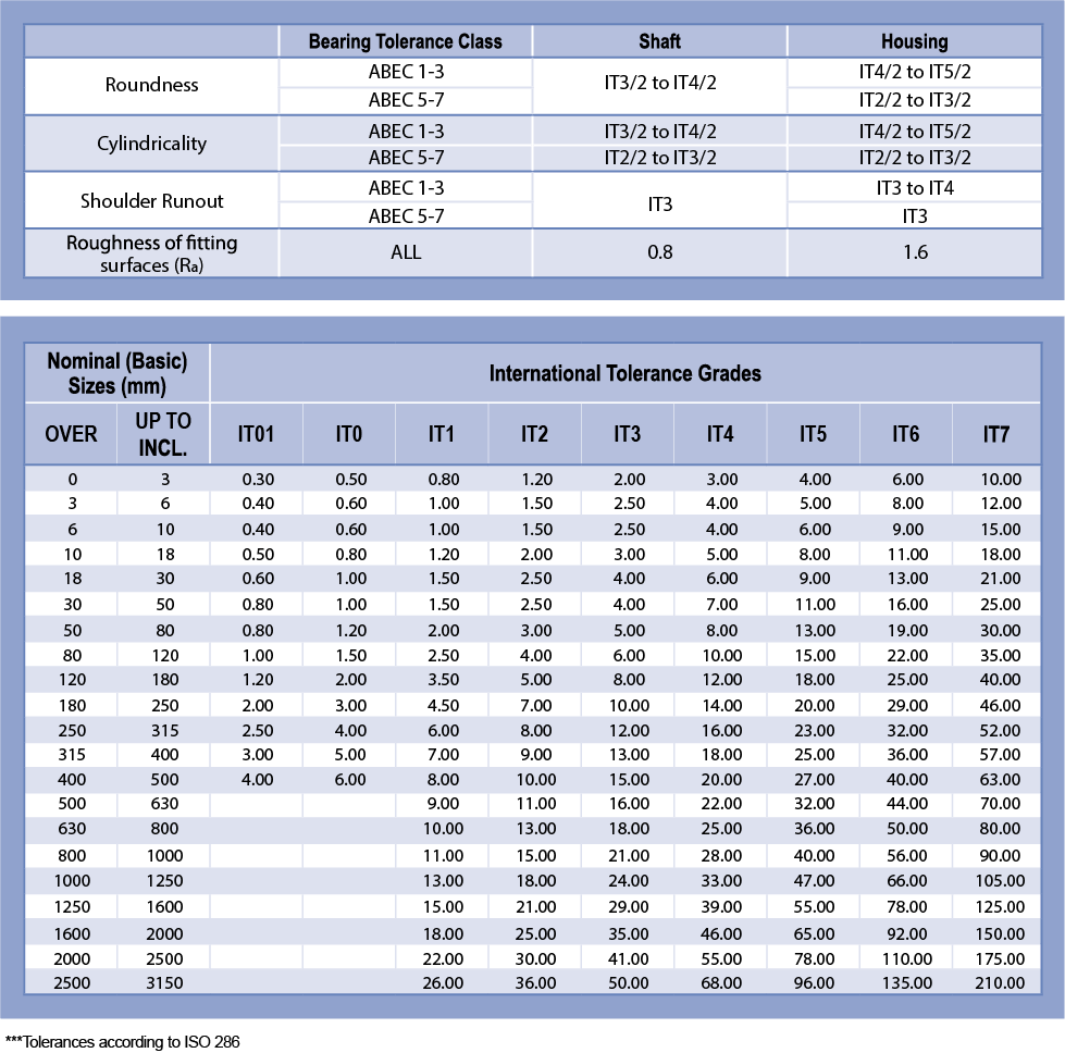
Preload
The purpose of applying preload to a bearing is to improve the runout precision of the rotating axis, and to reduce vibration and noise. It is important to select the proper amount of preload and method for each application. Otherwise, bearing performance such as life, noise, and vibration will be degraded. Excessive heat could also be generated.
The Purpose of Preload
The necessary radial internal clearance in an assembled ball bearing may increase noise and rotational vibration in an application due to the movement of the balls inside the bearings. To combat the relative movement of the balls, an axial “preload” should be applied to the bearing, as shown in the diagram below. Preload increases the stiffness of the bearing and reduces potential noise and vibration.
The appropriate preload force depends on the size of the ball bearing. Higher preload will increase the bearing stiffness but excessive preload may result in premature failures. If insufficient preload is applied, vibration and fretting wear may occur inside of the bearing.

Optimum Preload
Minebea recommends an optimum preload based on the calculation of the optimum surface stress. When the preload is applied to the ball bearing, a contact ellipse is generated as a result of elastic deformation of the contact areas between the balls and raceways. The surface stress is given by dividing the loads, Q (ball loads), which are generated in the perpendicular direction at the contacts between the balls and raceways, by the surface areas of the contact ellipses.
In Figure 2-15, the contact ellipse area (S) between the balls and raceways is formulated as: S = πab (a: the major axis of the contact ellipse area, b: the minor axis of the contact ellipse area). P represents the average surface stress, and Q represents the loads generated in the perpendicular direction at the contact areas between the balls and raceways.
P = Q / S [MPa]
If the preload is the dominant load applied to the bearing, the guideline to meet the noise life is as follows.
- Over 10,000 hours noise life requirement – The specific preload should not generate an average surface contact stress (P) higher than 800MPa.
- 5,000 – 10,000 hours noise life requirement (general products) – The specific preload should be generating an average surface contact stress (P) of roughly 1,000MPa.
- Less than 5,000 hours noise life requirement (critical stiffness application) – The specific preload should be generating an average surface contact stress (P) of roughly 1,500MPa.
Simple calculation of preload using dynamic load rating (Cr)
- Over 10,000 hours noise life requirement: 0.5/100Cr – 1/100Cr
- 5,000 – 10,000 hours noise life requirement: 1/100Cr – 1.5/100Cr
- Less than 5,000 hours noise life requirement: 1.5/100Cr – 2/100Cr
Maximum Permissible Load
In general, a permanent deformation will occur if the average surface stress generated on high carbon chromium steel is greater than 2,700 MPa. So, even for a very short period of time, the loads should not generate greater than 2,700 MPa of average surface stress. Based on our experience, the loads applied to the bearing should not generate more than 1,600 MPa of average surface stress. Besides preload, other types of loads should also be considered because they could generate surface stress.
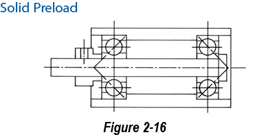
Preload and Stiffness
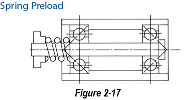
There are two basic methods of preloading: Solid Preload (Figure 2-16) and Spring Preload (Figure 2-17) shown on the following pages.
Solid Preload can be obtained by mechanically locking all of the rings in position. The advantages of this type of design are simplicity and high stiffness. However, expansion and shrinkage of the components due to temperature change can cause changes in preload. The components could also wear, and eventually the preloads could be reduced.
Spring Preload (constant pressure preload) can be applied by using a coil spring, wave spring, etc. An advantage of spring preload is stability despite temperature variation. The disadvantages are complexity and low stiffness.
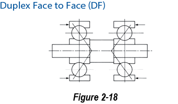
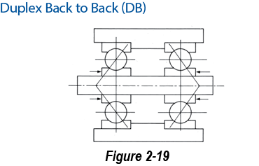
The preload can be applied in two directions: Duplex Face to Face (DF) (Figure 2-18) and duplex Back to Back (DB) (Figure 2-19). The stiffness is higher in DB.
Preload Method
Preload Direction
Torque
The torque in ball bearings depends on assembly, preload, enclosures and lubricants. These need to be selected based on the required specification.
Torque
There are two kinds of torque: starting torque and running torque. Starting torque is the initial torque required to rotate a bearing in the static state. A ball bearing in the static state has the elastic contact deformation generated between the raceways and balls if the loads, like preload, are applied to the shaft. A force to overcome the elastic contact deformation is required to rotate the bearings. Also, a force to overcome the lubricant fill between the balls and raceways is required. The total torque required to overcome these is called “starting torque.”
In addition, running torque includes friction between the balls and retainer and balls and the raceways.
The running torque has an impact on heat generation. In a motor application, bearing torque has an influence on the startup current, current rating, speed rating, current fluctuation, and speed fluctuation. The following are some of the factors and solutions.
Failure to Reach Speed
Some motors fail to reach the designed nominal speed. This could be caused by an excessive amount of grease, excessive interference fit, excessive preload, and use of churning type grease.
Excessive Startup Current
The possible factors to be considered for excessive startup current are: grease fill amount, high viscosity greases, preload, and fit conditions.
Speed Fluctuation
Speed fluctuation is the phenomenon where the rotation speed fluctuates unexpectedly and goes back to stable rotation speed after a while. This can be seen when grease loses its channel (wall) and is caught between the balls and raceways changing running resistance momentarily. Decreasing the grease fill amount, changing the grease to higher channeling grease, or non- churning type are options to prevent having this issue.
Speed and Running Torque
Generally, torque increases as speed increases. Preload and grease are selected based on the speed.
Grease Fill Amount & Running Torque
Generally, torque increases as the grease fill amount increases. Life could be adversely affected if the grease fill amount is reduced for the purpose of lowering the torque.
Temperature & Running Torque
Generally, running torque increases as the temperature decreases. The reason for this is that the temperature reduction increases the viscosity of the base oil in the grease.
Grease Fill Position & Running
Torque Running torque may vary based on the grease fill position. Especially with viscous greases, the shear force of the grease can affect torque.
Load and Running Torque
Load affects both the starting and running torque. The torque is higher if preload is applied.
Noise
Noise level is checked by an Anderon meter, which is explained below.
Anderon Meter

It is impossible to see the interior of the bearing once it is assembled. The noise levels of bearings must be checked when they are rotating. The Anderon meter checks the noise of assembled bearings and displays the noise level. In order to accurately perform the noise evaluation, the bearings are preloaded. The bearing’s inner ring is rotated at 1,800 RPM and the outer ring is stationary during the measurement. Mechanical vibration of the bearings outer ring is detected in the radial direction by contacting the outer ring with a velocity sensor. The signal from the sensor is converted to a variable electrical output. It is possible to detect even small vibrations because a direct detection system is used instead of a system that converts from rotational vibrations to air vibrations. Vibration from other sources can be eliminated in this method.
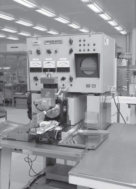
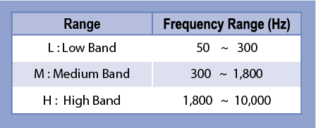
The detected vibration is classified into three different frequency bands. The unit for the Anderon meter is referred to as the Anderon value.
Compatibility with Plastic Parts
Some plastics are susceptible to degradation and cracking due to the lubrication used in ball bearings. Minebea does chemical tests for plastics and grease compatibility.
Chemical Attack
Depending on the chemical compatibility, plastic parts such as housings in some application could be degraded by the grease inside the bearings or rust preventative oils on the exterior.
This phenomenon is called a chemical attack. A chemical attack can occur in some combinations of plastic materials and lubricants. There are many factors that affect the chemical attacks.
When some physical force is applied to the plastics, grease penetration can cause the chemical attacks.
Stress of Plastic Parts
Internal residual stress can occur within injection molded plastic parts. This can be relieved by a secondary process such as machining or ultra-sonic adhesion. Although internal residual stress decreases slowly by gradual alleviation and annealing treatments, it is difficult to remove completely.
Oil and Grease
Ester is a common base oil of grease. Compared to other types of oil, chemical attacks occur in ester oil more often because it tends to penetrate plastics easily. Some types of oil such as Synthetic Hydrocarbon, Silicone, and Fluorinated resist oil penetration more effectively.
Weld Line
In injection molding, weld lines may reduce the mechanical strength of the part, leaving them vulnerable to penetration and chemical compatibility issues with the lubricant. Interference fit may also present issues at the weld lines.
Plastic Materials
While chemical attack tends to occur more in non-crystalline plastics (PS: Polyethylene, ABS, PC: Polycarbonate), crystalline plastics (PP: Polypropylene, PE: Polyethylene, POM: Polyacetal) have stronger resistance against chemical attack. Lubricants penetrate into intermolecular spaces more in non-crystalline plastics, and intermolecular bonding tends to break easily.
Plastic Compatibility
Plastic compatibility issues are less common if the internal stress is reduced and the appropriate grease is selected. Minebea has developed synthetic greases that provide improved resistance against plastic compatibility issues.
Lubricants
Lubricant selection has a strong impact on ball bearing performance. Bearing performance such as life, torque, rotation stability, and noise depends on lubricants even if the bearings use the same material and components.
Bearings are typically filled with either grease or oil. After the initial fill, the grease or oil is rarely changed or replenished. Generally, grease is standard in enclosure type bearings (bearings with seals or shields) because the life of grease is longer than that of oils.
Grease is composed of thickener and base oil. Fiber bonding and oil separation of the thickener plays an important role in grease. Fiber bonding keeps the oils in, and the oils are released gradually by oil separation. If only oils were filled in the bearings, they would tend to leak out of the bearing. The slow release of base oils due to oil separation makes longer lubrication life possible. When an application requires extremely low torque or torque fluctuations needs be minimized, oils are the preferred choice. This is because oils spread more than grease but greases are semi-solid and could add resistance against rotation. Grease performance may be enhanced by additives such as oxidation-resistant agents, lube agents (improving boundary lubrication), extreme pressure agents, and rust-inhibitor agents.
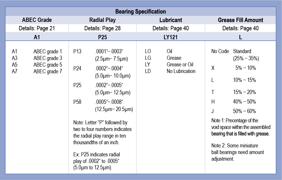
Lubricant Fill Amount
The standard lubricant fill amount for small and miniature size bearings is 25-35%. Grease fill amount varies in each application, and is specified as follows.
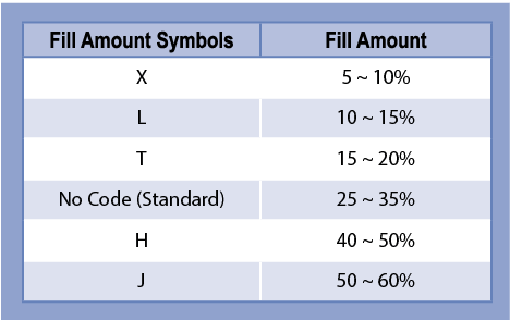
Table of Commonly Used Lubricant Types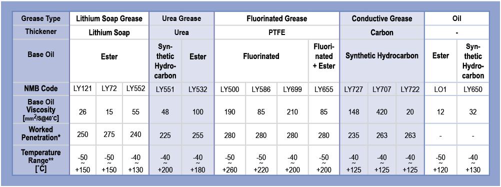
Application Guide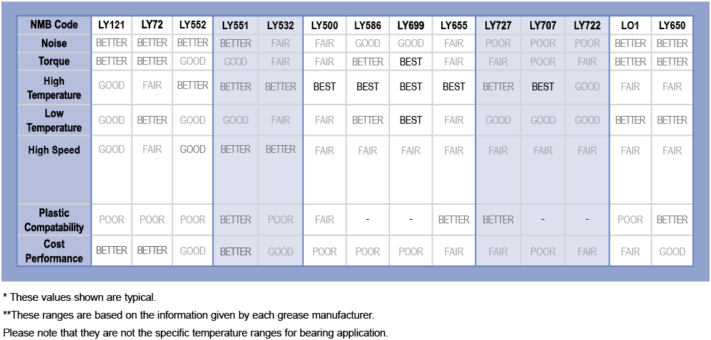
Handling of a Bearing
Ball bearings can be damaged from improper handling or installation. This may shorten the life due to noise, vibration, and heat generation. Careful handling is also required during shipping and storing. If adhesive needs to be used, please use it with a full understanding of its characteristics.
Ball bearings favor clean environments as they are very precise mechanical parts. Please maintain clean environments for their usage.
Installation of a Ball Bearing
There are many methods to install bearings onto shafts or into housings. The following are important for the installation process.
When bearings are assembled to either shafts or housings, by any fit methods, their centers must be aligned (Figure 2-28). If an interference fit is used, the pressing force has to be applied to either the inner ring or outer ring side face at a right angle. Apply the load slowly and continuously without the use of a shock or impact load.
Brinelling damage can occur when loads are applied in the wrong positions and/or when excessive loads due to misalignment are applied to the bearing during installation. If the bearing has enclosures, installation loads should not be applied to them.
Handling of Shafts and Housings
If shafts and housings are contaminated, bearing misalignment may occur during the installation (Figure 2-30). The same thing happens when the shaft and housing are scratched. If the bearing is pressed with these conditions, shafts and housings will be damaged further.
Since the inner and outer rings of ball bearings are very thin, the raceways will be affected easily by the shapes of shafts and housings when they are installed with interference fits. Inner and outer rings could be deformed easily, especially when shaft or housing roundness is poor. As a result, noise will increase and life will be shortened.
Shipping and Storing After Assembly
Bearing damage can occur even after installation. If the motor experiences a strong impact through the shaft, brinell damage can occur on the internal surfaces of the bearings. False brinell damage or fretting may also occur from vibration of the assembly.
Assembling with Adhesive
If adhesive is used for bearing installations, please note the following: Rust preventative oils on the outer surfaces of ball bearings need to be wiped away. Please use clean cloths saturated with alcohol. Avoid the use of excessive amounts of alcohol as it may result in migrations into the bearing along with contamination.
A list of common adhesives is shown below. Please select an adhesive after confirming characteristics with the adhesive manufacturer.
- Liquid type: Anaerobic, heat cure, UV cure, visible light cure, etc.
- Liquid combined type: Room temperature cure, heat cure, etc.
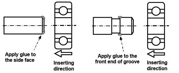
Adhesive amount should be minimized to prevent its ingress into the bearings. The anaerobic, UV and visible light type adhesives should be handled especially carefully because it is difficult to notice adhesive migration at the time of installation. Only the necessary amounts, as shown in Figure 2-31, should be applied. A shaft or housing groove for the adhesive is also effective.
Avoid exposing bearings to high temperature during the hardening process. Lower temperature is favorable for hardening. UV lighting devices could introduce excessive heat, so avoid using for long periods of time or under high power because some greases may migrate or degrade due to the temperature.
Cyanoacrylate adhesives could cause outgassing during hardening resulting in rotational issues.
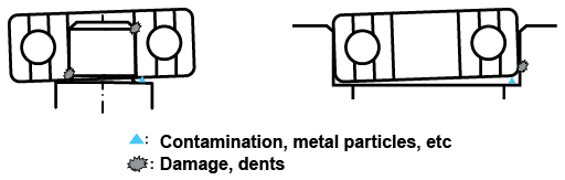
Handling During Insertion

Load Position for Press Fit

Misalignment Due to Contamination and Damage
Applying Adhesive (Examples)