Last Modified - March 13, 2026
Introduction
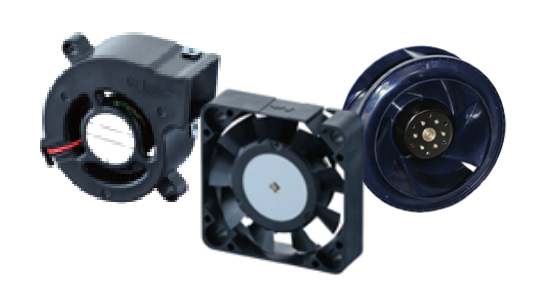
NMB Technologies Corporation (
"Company" or
"We") respect your privacy and are committed to protecting it through our compliance with this policy.
This policy describes the types of information we may collect from you or that you may provide when you visit the website nmbtc.com (our "
Website") and our practices for collecting, using, maintaining, protecting, and disclosing that information.
This policy applies to information we collect:
- On this Website.
- In email, text, and other electronic messages between you and this Website.
It does not apply to information collected by:
- us offline or through any other means, including on any other website operated by Company or any third party (including our affiliates and subsidiaries); or
- any third party (including our affiliates and subsidiaries), including through any application or content (including advertising) that may link to or be accessible from or on the Website.
Please read this policy carefully to understand our policies and practices regarding your information and how we will treat it. If you do not agree with our policies and practices, your choice is not to use our Website. By accessing or using this Website, you agree to this privacy policy. This policy may change from time to time (see Changes to Our Privacy Policy). Your continued use of this Website after we make changes is deemed to be acceptance of those changes, so please check the policy periodically for updates.
Children Under the Age of 13
Our Website is not intended for children under 13 years of age. No one under age 13 may provide any information to or on the Website. We do not knowingly collect personal information from children under 13. If you are under 13, do not use or provide any information on this Website or on or through any of its features. If we learn we have collected or received personal information from a child under 13 without verification of parental consent, we will delete that information. If you believe we might have any information from or about a child under 13, please contact us at: GDPR@nmbtc.com
Information We Collect About You and How We Collect It
We collect several types of information from and about users of our Website, including information:
- by which you may be personally identified, such as name, postal address, e-mail address, telephone number ("personal information");
- that is about you but individually does not identify you; and/or
- about your internet connection, the equipment you use to access our Website and usage details.
We collect this information:
- Directly from you when you provide it to us.
- Automatically as you navigate through the site. Information collected automatically may include usage details, IP addresses, and information collected through cookies.
Information You Provide to Us. The information we collect on or through our Website may include:
- Information that you provide by filling in forms on our Website. This includes information provided at the time of subscribing to our service or requesting further services. We may also ask you for information when you report a problem with our Website.
- Records and copies of your correspondence (including email addresses), if you contact us.
If available, you also may provide information to be published or displayed (hereinafter, "
posted") on public areas of the Website, or transmitted to other users of the Website or third parties (collectively, "
User Contributions"). Your User Contributions are posted on and transmitted to others at your own risk. Although we limit access to certain pages, please be aware that no security measures are perfect or impenetrable. Additionally, we cannot control the actions of other users of the Website with whom you may choose to share your User Contributions. Therefore, we cannot and do not guarantee that your User Contributions will not be viewed by unauthorized persons.
Information We Collect Through Automatic Data Collection Technologies. As you navigate through and interact with our Website, we may use automatic data collection technologies to collect certain information about your equipment, browsing actions, and patterns, including:
- Details of your visits to our Website, including traffic data, location data, and other communication data and the resources that you access and use on the Website.
- Information about your computer and internet connection, including your IP address, operating system, and browser type.
The information we collect automatically is statistical data and does not include personal information, but we may maintain it or associate it with personal information we collect in other ways or receive from third parties. It helps us to improve our Website and to deliver a better and more personalized service, including by enabling us to:
- Estimate our audience size and usage patterns.
- Store information about your preferences, allowing us to customize our Website according to your individual interests.
- Speed up your searches.
- Recognize you when you return to our Website.
The technologies we use for this automatic data collection may include:
- Cookies (or browser cookies). A cookie is a small file placed on the hard drive of your computer. You may refuse to accept browser cookies by activating the appropriate setting on your browser. However, if you select this setting you may be unable to access certain parts of our Website. Unless you have adjusted your browser setting so that it will refuse cookies, our system will issue cookies when you direct your browser to our Website.
- Flash Cookies. Certain features of our Website may use local stored objects (or Flash cookies) to collect and store information about your preferences and navigation to, from, and on our Website. Flash cookies are not managed by the same browser settings as are used for browser cookies. For information about managing your privacy and security settings for Flash cookies, see Choices About How We Use and Disclose Your Information (below).
We do not collect personal information automatically, but we may tie this information to personal information about you that we collect from other sources or you provide to us.
How We Use Your Information
We use information that we collect about you or that you provide to us, including any personal information:
- To present our Website and its contents to you.
- To provide you with information, products, or services that you request from us.
- To fulfill any other purpose for which you provide it.
- To carry out our obligations and enforce our rights arising from any contracts entered into between you and us, including for billing and collection.
- To notify you about changes to our Website or any products or services we offer or provide though it.
- In any other way we may describe when you provide the information.
- For any other purpose with your consent.
Disclosure of Your Information
We may disclose aggregated information about our users, and information that does not identify any individual, without restriction.
We may disclose personal information that we collect or you provide as described in this privacy policy:
- To our subsidiaries and affiliates.
- To contractors, service providers, and other third parties we use to support our business and who are bound by contractual obligations to keep personal information confidential and use it only for the purposes for which we disclose it to them.
- To a buyer or other successor in the event of a merger, divestiture, restructuring, reorganization, dissolution, or other sale or transfer of some or all of NMB Technologies Corporation's assets, whether as a going concern or as part of bankruptcy, liquidation, or similar proceeding, in which personal information held by NMB Technologies Corporation about our Website users is among the assets transferred.
- To fulfill the purpose for which you provide it.
- For any other purpose disclosed by us when you provide the information.
- With your consent.
We may also disclose your personal information:
- To comply with any court order, law, or legal process, including to respond to any government or regulatory request.
- and other agreements, including for billing and collection purposes.
- If we believe disclosure is necessary or appropriate to protect the rights, property, or safety of NMB Technologies Corporation, our customers, or others.
Choices About How We Use and Disclose Your Information
We strive to provide you with choices regarding the personal information you provide to us. We have created mechanisms to provide you with the following control over your information:
- Tracking Technologies and Advertising. You can set your browser to refuse all or some browser cookies, or to alert you when cookies are being sent. To learn how you can manage your Flash cookie settings, visit the Flash player settings page on Adobe's website. If you disable or refuse cookies, please note that some parts of this site may then be inaccessible or not function properly.
We do not control third parties' collection or use of your information to serve interest-based advertising. However these third parties may provide you with ways to choose not to have your information collected or used in this way. You can opt out of receiving targeted ads from members of the Network Advertising Initiative ("
NAI") on the NAI's website.
Changes to Our Privacy Policy
It is our policy to post any changes we make to our privacy policy on this page. If we make material changes to how we treat our users' personal information, we will notify you. The date the privacy policy was last revised is identified at the top of the page. You are responsible for ensuring we have an up-to-date active and deliverable email address for you, and for periodically visiting our Website and this privacy policy to check for any changes.
Contact Information
To ask questions or comment about this privacy policy and our privacy practices, contact us at: GDPR@nmbtc.com
NMBTC ISO Quality Policy